Circuit variant:
- 1. Button as a clock (labs 4,5)
- 2. Button as a write enable
- 3. Button as an FSM input (labs 6,7)
Button as a clock
This circuit uses BTNL as a clock source. This is generally a bad practice (for many reasons, see BI-PNO and others for more). In labs 4 and 5, we allow it. Later, we don't.
To do things right, all clock inputs (triangle) must be connected to the same clock signal. Correct way to achieve the same behavior is shown in circuit variant 2.
In your final assignment (labs 6,7), you may need to think of the button as one of the FSM inputs, as shown in circuit variant 3.
Button as a write enable
This circuit uses BTNL as a write enable (we) signal. The flip flops are clocked using common 100MHz clock. This is a correct way to implement behavior of this simulator.
Note that 100MHz clock means 100 million clock edges per second. If you would connect BTNL directly to write enable, and then you would press the button for one second, the FSM would make 100 million steps. See the Rising edge detector (in circuit) for a solution.
However, this solution also means that FSM can do a step only when you press the button. For more complex tasks, you may need circuit variant 3.
Button as an FSM input
The most universal solution uses the button as an FSM input. This may be your only choice in your final assignment. It is not implemented in this simulator!
The FSM will now do 100 million steps per second (whether it goes to another state, or stays in the same state). It is now your responsibility to design the FSM so it will wait for the button press (or do whatever else you need it to do).
Note that the FSM should typically also wait for button release. Or, instead of waiting for release, you may again use the Rising edge detector.
Digital systems are all about accuracy. How precise and accurate is a signal from button? It may look like this:
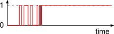
When you press the button, first, the physics happens. Suddenly, where you were expecting a single rising edge, there are six! Similar thing will happen again when you release the button. This "noise" must be filtered by the Debouncer block.
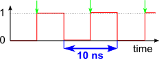
Clock signal is a periodic rectangular signal. Flip flops react to its rising edges (green). In our case, it has frequency 100 MHz:
In the circuit variant 1 (labs 4 and 5), we don't use this clock signal for our FSM. We use BTNL instead.
The variants 2 and 3 are synchronous circuits, meaning that all their sequential logic (flip flops) is connected to the same clock signal. This will be required in the final assignment (labs 6 and 7)
The clock signal is fast. It's very fast. If you want to control your FSM with a button, you would have to be very fast too. Because while you are holding the button, write enable (or other) signal is active, and millions of transitions (steps) keep happening.
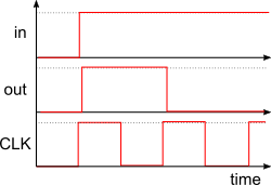
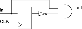
One way to deal with this is a rising edge detector. It transforms a long pulse into a short single-clock cycle pulse. In circuit variant 2, this means a single FSM step will happen, no matter how long you hold the button:
And it's pretty easy to implement:
There are multiple ways to trigger a single event in FSM. Let's say we want to build a switch using a button. One press turns output on. Second press turns output off.
With a rising edge detector
In both states, the FSM waits for the button to be pressed. Thanks to the edge detector, only a single pulse is generated. Without the detector, the FSM would quickly switch between states, and the result would be random (in fact, awesome random number generator!).
Without a rising edge detectorSometimes, this may still not be enough for us. Let's say we want to detect both button press and release. We could either use two edge detectors, or we can do the same thing with the FSM:

This combinatorial logic block implements the FSM transitions. In other words, it decides what the next state is going to be.
Its inputs are the current FSM state (q0,q1,...) and the input signals (SW0,SW1,...).
Its output is next FSM state (d0,d1,...).
Flip flops/registers are elementary memory blocks. With every rising edge on clock input, they write the input value d to the output q, and keep it there until the next rising edge.
If the flip flop has a write enable (we) input, it performs the write only if the we signal is active. Otherwise, it keeps remembering the old input.
In our case, these flip flops remember the current FSM state. If there are N different states, there must be at least ceil(log2(N)) flip flops. These two could only work with 4 different states.
This combinatorial logic block implements the FSM output. In other words, it decides what the output is going to be.
In Moore FSM, its input is current state (q0,q1,...).
In Mealy FSM, its inputs are current state (q0,q1,...) and input signals (SW0,SW1,...).
What is the difference between counter in binary code, one-hot code, and Gray code? Output logic/decoder!